Friday, 1 November 2013

WEEK 7 (Software Development)

For software development we have use the Microcode Studio software.

MicroCode Studio is a powerful, visual Integrated Development Environment (IDE) with In Circuit Debugging (ICD) capability designed specifically for microEngineering Labs PICBASIC PRO™ compiler. Compilation and assembler errors can easily be identified and corrected using the error results window. Just click on a compilation error and MicroCode Studio will automatically take you to the error line. MicroCode Studio even comes with a serial communications window, allowing to debug and view serial output from microcontroller.

The MicroCode Studio ICD communicates with the microcontroller using its hardware USART.  Refer the the Microchip data sheet for the microcontroller used if unsure which pins the device uses for its USART. For example, the PIC16F877A uses PORTC.7 for RX and PORTC.6 for TX. The ICD will work with microcontrollers running at different clock speeds.  However, it is essential that your PBP code has the correct oscillator setting defined. By default, this is 4MHz.


More extensive micro coding has also been used to allow small and simple micro architecture to emulate more powerful architecture with wider word length, more execution units etc; a relatively simple way to achieve software compatibility between different products in a processor family.
            To develop program in the PIC, microcode have been used to program the sensor so that it applicable of the chicken coop environment. Actually microcode is easily to be used and understand for the beginner programmer. It does not have to see the difficult term to write the programmed.


Friday, 25 October 2013

WEEK 6 (Troubleshoot Circuit)


Hardware testing involved a systematic approach to built interfacing circuit which is beginning with testing the component and connection.After the connection is functional, the full circuit is construct. However, there are a few problems faced during the hardware development such as the speaker is not functioning and the connection loss between control panel circuit and GSM modem that cause the alert message was not delivered. . Then the circuit was troubleshoot by changing the speaker and RS 232 cable with the new one and solder it to the circuit as shown in figure below.


Saturday, 19 October 2013

WEEK 5 (Soldering)

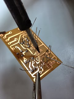
After we had done the PCB processes, we solder the component on the completed UV board. We also tested the components using multimeter.
We do the soldering in our supervisor's lab at level 2, the electronic section.


Friday, 11 October 2013

Friday, 4 October 2013

WEEK 4 (PCB process)

This week, we were doing the cutting & etching process.Plus we also survey the price and components for this project. We have bought all the things needed to process with the next process that is soldering the circuit.


Cutting the UV board


UV board & outline circuit


Etching process


Friday, 27 September 2013

WEEK 3 (PCB outline)

Before we start doing the etching process, we did the circuit outline first. For the outline, we used DipTrace software.
DipTrace software


These are the circuit outlines :

IR Sensor


Voice Recorder Module


Friday, 20 September 2013

WEEK 2 (Research & Components)

We did some research on The Deepest Bin. However, there were not many information on this project, but there was an example of smart dustbin on the youtube that was similar to our project. Here is the link of the smart dustbin >> http://www.youtube.com/watch?v=cbEKAwCoCKw
Back to our project, instead of making the dustbin as an attraction, we add on GSM technology to increse the efficiency of the waste management system.

These are the components that we are going to use for the Hardware: infrared sensor, PIC 16F877A, GSM modem and voice recorder module.

BLOCK DIAGRAM

The figure above is a block diagram for the deepest bin project using GSM Technology. Infrared sensor will work entirely by detecting the energy given off by the thrower. When the sensor detects movement, the voice recorder module will produce sound like a very long fall followed by a large crash. By placing a simple sound effect it will encourage people to properly disposing waste. When the trash is full, the infrared sensor that is also connected to the microcontroller will give command to GSM modem. The GSM modem will then send a text message to the garbage collector. By implement this project it will help to increase the efficiency of waste management system.


***************          

           Final year project briefing was held together with the internship briefing at TTL hall. The attendence was compulsory for all students who are taking final year project this semester. The briefing started at 3.00pm to 5.00pm. The final year project briefing was conducted by FYP's commitees. The briefing was all about:-

- the scheme of work for final year project.
- make a logbook or a blog for final year project and must be updated every week to show project progression.
- every student can claim RM300 per person for the project.
- always meet the supervisor regarding the project.

Our supervisor is Mr Azman from the Electronic Section, level 5.

Encik Azman Aziz